Beam diagnostics at the Canadian Light Source
J.C. Bergstrom et al., from the Canadian Light Source (CLS) applied the unique capabilities of the 4 Picos ICCD camera for synchrotron beam diagnostics with high spatial and temporal resolution.
Ultra high speed camera 4 Picos for synchrotron beam diagnostic measurements
Various tools and equipment are used to measure and monitor the beam parameter of any synchrotron facility. At the Canadian Light Source (CLS) the 4 Picos ICCD camera is used to supplement these numerous gadgets. Due to its shortest gating time of 200 ps it is highly versatile in its ability to "slice and dice" the bunch train, and to stack images of the same bunch on multiple turns, which gives the ability to observe quadrupole-like instabilities of the beam or the beam parameter mismatch at injection to the storage ring.
The CLS completed its commissioning phase of operations in 2003 and became a member of the rapidly growing community of synchrotron light facilities. The CLS operates at nominal energy of 2.9GeV and the numerous beamlines are supplemented by two independent diagnostic beamlines called the Optical Synchrotron Radiation (OSR) and the X-ray Synchrotron Radiation (XSR). The 4 Picos ICCD camera is used in the OSR beamline, which operates in the visible region.
Beam diagnostic measurements at OSR
The OSR beamline basically consists of a vertical chicane which is used to separate the optical synchrotron radiation from the X-ray component, a pick-off mirror to gather the light, a large lens to provide a 1:1 image on the optical table and a series of beam splitters and relay lenses to channel the light to the camera. The 4 Picos intensified camera enables measurements with high spatial resolution and excellent temporal resolution due to its high speed shutter. Furthermore, J. Bergstron noticed in his article: "With a minimum gating window of 300ps, the ICCD camera lets walk down a bunch train and monitor the emittance on a bunch-by-bunch basis."
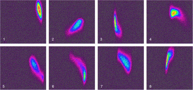
Beam diagnostic along a bunch train.
The camera control of the 4 Picos camera allows nearly arbitrary delays between multiple shots. This enables beam diagnostic measurements as walk along the bunch train during the CLS commissioning phase. The crew of Bergstrom photographed every 10th bunch and could thereby determine a signature of the fast beam-ion instability (FBII). The FBII is a single-pass phenomenon unlike the usual ion trapping instability. The argument in favour of the FBII is augmented by the relatively poor vacuum during commissioning and by the fact that the instability disappeared with time as the vacuum improved.
ICCD camera is unique in its beam diagnostic capability
The determination of the FBII instability illustrates the unique feature of the ICCD camera, namely the ability to observe quadrupole-like instabilities which are invisible to the storage ring beam position monitors, since there is no motion of the bunch center of mass. Therefore, Bergstrom reiterate: "the ICCD camera is unique in its capability to image the beam from the front, with both high spatial resolution and moderate temporal resolution.".
Injection study with the ICCD camera 4 Picos
The ICCD camera has found an interesting other application during machine set-up operations. By monitoring the beam profile on a turn-by-turn basis immediately following injections, one can easily discern if there is a serious mismatch between the Twiss parameter of the injected beam and those of the storage ring. As it can be see in the figure above the variation in profile from turn to turn indicates that the injected beam is not optimally matched to the phase space parameters of the storage ring, most notably in the horizontal plane.
Title: The optical diagnostic beamline at the Canadian Light Source
Author: J. C. Bergstrom and J. M. Vogt
Institute: Canadian Light Source,
Saskatoon, Canada
Similar Application at the Australian Synchrotron Storage Ring:
Title: X-Ray and Optical Diagnostic Beamlines at the Australian Synchrotron Storage Ring
Author: M. J. Boland, et al.
Institute: Australian Synchrotron, Clayton, Australia